

How To Change A Pressure Relief Valve On A Furnace
Terminal updated: August 24, 2020
Most of us are very familiar with the pressure relief valve and pressure reducing valve. Both valves command the pressure level in the hydraulic system. Since both are force per unit area controlling device still both are different from each other. Therefore, we volition learn in this article how they differ with each other, where it tin exist used, and their construction. As well, we will see some special-purpose valves.
Pressure relief valve
Consider a uncomplicated hydraulic system without a relief valve for example.
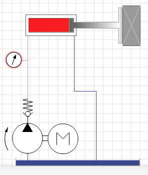
When the pump starts and does the piece of work by lifting the load upwards to its maximum limit. But when it reaches its limit what will happen? The pump is still running and tries harder to button more than oil in the system and ultimately pressure will increase tremendously and damage the weaker component. Therefore nosotros need something which will limit the pressure in the system. This component is a pressure relief valve.
Pressure relief valve: A pressure relief valve is a hydraulic component that provides safety to the hydraulic system from excessive force per unit area. This is normally closed but when the pressure in the hydraulic system increase across the set limit of a pressure relief valve, information technology opens the path and allows hydraulic oil to catamenia into the tank. In this way, it releases the excessive pressure level from the arrangement and provides protection. As shortly as pressure reduces in the system, the pressure relief valve comes in the initial position and closes the open path once again.
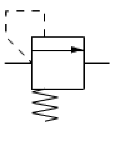
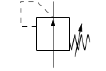
As shown to a higher place, an pointer shows the airtight path for hydraulic fluid and there is too spring tension which forces the relief valve to remain airtight. But when the pressure in the hydraulic organization is enough or more than than relief valve spring tension, a pilot line will push the arrow against the spring tension and open the path. In this way, the pressure is relieved from the system and salve the components.
Click to acquire Industrial Hydraulic Symbols.
Structure of force per unit area relief valve
A pressure relief valve can be designed in many more ways but, here it is the well-nigh common type of pressure relief valve. It consists of 2 passages one is
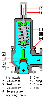
As in higher up figure 4, you can run into at that place is a valve seat which is normally closing the inlet and seat holder is forced against a spring. At the superlative, there is a screw which will set the spring tension or in other give-and-take ready the pressure of the relief valve. Ordinarily, the screw is protected with a cap so, the unauthorized person can not change the pressure setting and also it protects the screw from rusting.
Pressure Reducing Valve
Pressure reduction valves are used to limit the hydraulic pressure in a system. Notwithstanding, instead of reducing inlet pressure, they reduce the outlet pressure. It divides a hydraulic system into dissimilar sub-systems. For Case, If a hydraulic system there are numbers of operations, and each has its own capacity. As per every hydraulic component, there may exist a different pressure requirement but with only one pump this cannot be accomplished but with the utilize of pressure reducing valve it tin can hands achieve.
Force per unit area reducing valve is normally open valve and it allows the pressurized fluid to period but when the pressure level at the output of the valve is more than than the valve force per unit area setting, a pilot force per unit area pushes the arrow down and the path volition close. The valve will not permit pressurized fluid to flow in the system until the force per unit area drops lower than the valve pressure level setting.
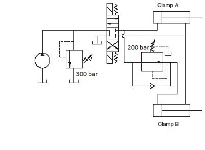
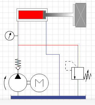
In the above case, there are 2 hydraulic actuators for clamp A and B which holds a workpiece. A pressure relief valve. A pressure reducing valve. And a direction command valve and positive deportation pump. The pressure level relief valve setting is 300 bar. So, the maximum arrangement pressure is 300 bar. When the direction control valve is in the first position both the clamp cylinders extend but in clamp A the pressure will be maximum as system pressure but in clamp B due to the pressure reducing valve setting, the pressure will be 200 bar. Equally soon as the pressure increases in the clamp B line the force per unit area reducing valve will close and non allow the pressurized fluid to flow. Hence, the pressure volition limit at 200 bar.
For better understanding, yous may read click hither this article.
Structure of pressure level reducing valve
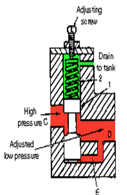
A common pressure reducing valve consists of an inlet port (C), an outlet port (D), and a pilot line (E). There is a spool against the spring tension which opens and closes the path for pressurized fluid. As the pressure increase at the outlet port (D) beyond the spring tension (i.e. Pressure setting), pilot line (Due east) shift the spool against the spring and make the opening narrow. Due to the
FAQ about pressure relief valve and force per unit area reducing valve
- What exactly happens if the pressure relief valve replaced by a reducing valve?
Reply: The function of a pressure relief valve is to limit the maximum pressure level in a hydraulic organization. It closes normally and opens simply when the organization pressure level exceeds the setting of the force per unit area relief valve, by releasing pressurized oil to the lower pressure side or tank. Whereas on the other hand, the force per unit area reducing valve limits the pressure for the system to less than the maximum pressure. It opens usually and closes only when the organisation force per unit area at the output of the reducing valve exceeds its gear up pressure. Just if we supercede a pressure level relief valve with a pressure level reducing valve, the required pressure cannot be generated. Because there is no longer the necessary restriction to generate pressure level and the flow will be directed to the tank due to their constructional difference. For more understanding Read hydraulic symbols.
Hope, you like this article and learned the basic of pressure relief valve and pressure reducing valve.

Source: https://www.stuffworking.com/pressure-reducing-valve-pressure-relief-valve/
Posted by: espinozaexuld1949.blogspot.com
0 Response to "How To Change A Pressure Relief Valve On A Furnace"
Post a Comment